LINE OF SIGHT - THE REAL RANGE OF WIRELESS COMMUNICATIONS

In this universal context, wireless signal interferences have been catalogued to differentiate the existing obstructions.
The success of wireless communications depends on the environment in which communication occurs. The exchange of data between transmitters and receivers via wireless communication requires that the best conditions are compiled for this operation to be carried out effectively. When we are working on wireless communications, in addition to the need to use equipment and components with the intended application characteristics, it is essential to analyze the physical environment between the communication points.
The space where communication takes place will always have several conditioning factors that lead to communication does not occur effectively or simply not occurs.
Usually, technicians and engineers consider the communication range feature that in addition to their unit of measurement comes with the abbreviation LoS, known as Line of Sight.
What is Line of Sight?
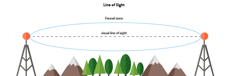
The most common meaning for this term refers to the line of sight between two points, where they can be observed directly to each other. However, the LoS, which is often referred to in the context of wireless communication, or more commonly in the diffusion of electromagnetic waves, in addition to the directional visual field between the points being clear, encompasses in this term the whole environment around that fictitious line, identified as Fresnel zone, which should be totally clear, so that the ideal conditions for the propagation for electromagnetic waves are recorded. The obstruction of this zone may be constrained by human construction (e.g. buildings) or by interference from natural sources (e.g. trees and mountains) or even by the curvature of the earth in the case of high communication distances.

Figure 1 - Ideal LoS communication scenario
Fresnel zone is an elliptical, three-dimensional area formed around the direct line of sight between the two communication points, formed of theoretically infinite layers of the same shape but with different sizes. The degree of interference in the communication increases as the obstruction approaches to the closest area from the visual field.

Figure 2 - Fresnel zone around Line of Sight
Fresnel zone radius calculation can be performed through a specific mathematical formula and considers the distance between the communication points and the wavelength of the signal.

Figure 3 - Fresnel zone radius calculation
- Fn = radius of the nth Fresnel zone (meters)
- d1 = distance from point P to one of the antennas (meters)
- d2 = distance from point P to the other antenna (meters)
- λ = wavelength of the transmitted signal (meters)
Near Line of Sight (nLoS) and Non Line of Sight (NLoS)
The fact that there is a clear field of view between the transmitter and the receiver does not guarantee that communication will take place in the best way possible once that the electromagnetic waves do not travel between the transmitter and receiver in a straight line exclusively. In this universal context, wireless signal interferences have been cataloged to differentiate the existing obstructions. Within the LoS chapter, we find derivations that help to clarify this issue.
Near Line of Sight
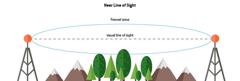
This term is applied when there are obstructions within the Fresnel zone but where the line of sight between the two communication points remains unobstructed. The presence of a partial occupation of the Fresnel zone does not block the communication signal but promotes the degradation of the transmitted signal quality.

Figure 4 - nLoS communication scenario
Non Line of Sight
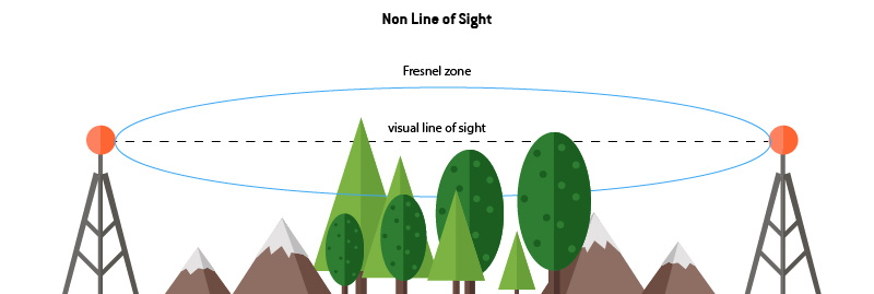
In this scenario, there is a physical barrier that partially blocks the first Fresnel zone and that completely blocks the visual line between the two communication points.

Figure 5 - NLoS communication scenario
In most everyday applications, we find situations where wireless communications between transmitters and receivers occur in a scenario where the field of view between them does not exist and where signal propagation occurs through other phenomena that help to ensure that the signal reaches their supposed receiver.
Basic propagation mechanisms
The propagation of the electromagnetic signal, when there is no environment conducive to optimal transmission, can occur through recognized phenomena in this area. These are events that occur with the interference of objects that are present in the environment surrounding the communication.
- Reflection – the propagation through reflection occurs when the signal is reflected in an object being routed in another direction;
- Diffraction – This propagation method occurs when an obstacle is on the communication line. Part of the electromagnetic wave acts as the source of a secondary wave that is created from the intersection point. Within the specialty, this phenomenon is known as the Huygens-Fresnel principle;
- Scattering – this process occurs when the object that is hit by the wave has a dimension equal to or less than the wavelength and diffuses the signal in all directions.
Conclusions
The Line Of Sight term has added a unique insight to all professionals working with dedicated equipment in this area about the limitations of communication ranges. The typical perception of this term refers to the line of sight and that the ideal conditions of LoS are mostly theoretical, making reality a default approximation.
In Tekon Electronics wireless product families, you can find the information you need about the Line of Sight features of our products. Check out our product pages and see which best suits your application.